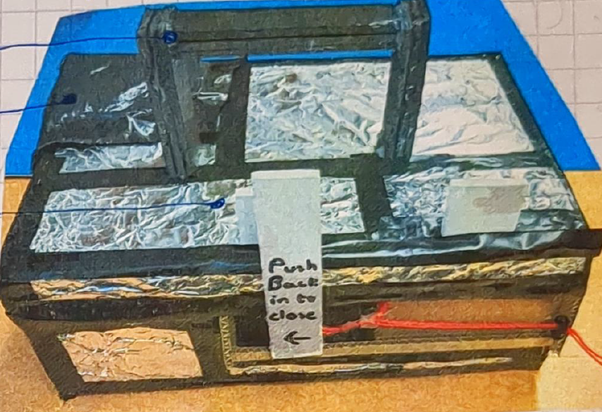
1. The Need
A simple camera made with materials found in an art studio for people with disabilities enrolled in the arts program.
2. User Needs and Constraints
Engineering is when a societal need is met using math, science, and technology. In our case we have the art studio for people with disabilities. These people need a camera to take photos of a 10 ft x 10 ft mural outside their art studio. The entire mural must fit into a 4 in x 5 in sheet of film paper and the image shouldn’t be too small or too big. They have limited range hand dexterity which is like a pair of oven mittens on your hands. So, the camera should be easy to grasp. The materials also need to be inexpensive and mostly be things that can already be found in the art studio. Finally, the pinhole camera must go along with a set of instructions on how to use it. While using the camera, the person must stand at least 5ft away from the mural. However, the courtyard in front of the art studio is only 20 ft x 20 ft. This makes for at most 15 ft of moving space. The problem of adapting a large mural onto a small sheet of film paper is solved via an aperture. It’s the small hole in the front of any camera letting a diffused amount of light in. These light rays bounce off the object that you are pointing at and directly enter through the aperture. If you move closer to the mural, the bigger the image will be on the film. The farther back you move, the smaller your image. Nonetheless, there are other factors that determine how your image will look like how long the focal length-the length between the aperture and the film. We take in a lot of elements like the distance between the camera and mural, the height of the mural and width of the film to get a variable distance of 2–8 inches.
3. Initial Concept Generation
Before going to the actual mind map and brainstorming various aspects of our camera, we had to find a suitable body for our camera. I decided to bring a shoebox as it was the exact height for the film paper. It was also structurally sound, and we could do many things with it without it deteriorating in capability. However, when you use a shoebox, it could be too wobbly for a person with hand dexterity to use. We started thinking about making a handle of some sort to easily solve this problem. Next, we did the flashlight test by putting some sort of light inside our box with the lid closed. We took the box to a darkroom as then we could see all the leaks in our box. We mostly had leaks in the corners and the sides where the lid closed. We decided for our camera that we need to fill these areas up so no light can be let in, and the picture comes out perfectly. When we looked at other people’s Light leak test results, we found that most of them were cardboard boxes with a few minor leaks that could be readily repaired.
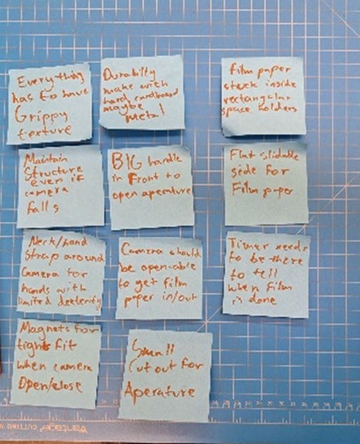
We first used sticky note brainstorming, which is basically to develop ideas quickly that meet a couple of needs on the camera. Such items include film paper stuck inside rectangular cardboard holders or a big handle on top of the aperture. The sticky note brainstorming helped us visualize these ideas and arrange them in a logical manner on our mind map later. We were able to generate and organize innovative concepts for our camera design more efficiently by using this method. My partner and I took these sticky notes and organized them into groups, with each group having ideas that met separate demands in the camera.
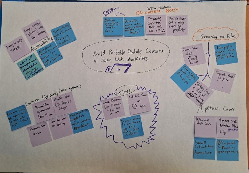
In our mind map, we put these ideas into groups. The plus side of having many ideas is that they allow us to find problems in some and adapt others. Additionally, this systematic approach enables us to brainstorm more effectively, as we can explore different angles and perspectives within each group. We analyzed each group to identify common themes and prioritize the most feasible ideas. This turned into our sliding mechanism later on. This process assisted us in narrowing our options and developing a comprehensive plan for improving the camera’s functionality.
Concept A — One of the concepts we developed was the aperture cover. We considered a sealing piece of cardboard that would flip and close the aperture. The discussion about this turned into an idea that would be beneficial to our camera later on. It was the slide-in mechanism in which the cover or holder would slide between two cardboard rails. This slide-in mechanism would not only provide a secure closure for the aperture but also allow for easy and quick access when needed.
Concept B — We thought of another concept with that slide-in mechanism employed, but this time it was for the film paper. More specifically, the job of securing it. We imagined a sliding tray into which you would insert the film, like a photo frame, except that the photo had not yet been taken. The slide-in tray would enter through a small inlet on the side of the shoebox, as the cover of the box would be completely taped shut.
Concept C — Another interesting concept we explored was for any camera opening, mostly for taking out and putting in the film. We thought of two large doors or flaps on any side of the box. This allows us to use our hands to get in the box and secure the film.
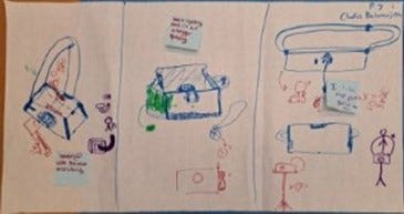
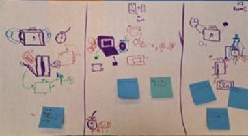
Design From C-sketch
We didn’t choose an exact C sketch as different people from other groups put things onto our initial idea. Instead, we looked though all the drawings to see which ones might fit our project well. After careful consideration, we finally decided to combine elements from various sketches that aligned with our project’s goals. This collaborative approach allowed us to incorporate diverse perspectives and create a unique and cohesive C sketch. We came up with two main elements that are beneficial to our design. This was the aperture cover and the film holder. For our aperture cover we used the slide in technique already outlined in the mind map section. However, we did add some extra things from people’s drawings on our c-sketches like a handle attached to the aperture cover so that you can easily pull it. For our film holder we got a few ideas from the C-sketching that just visualized what we were going to do. Although most of the C-sketches had us opening an entire side of the box, they also offered some solid suggestions for protecting the film. One of these is to add a photo frame-like structure to hold the film. So, I decided that merging both concepts would be beneficial because we now have a dependable film holder and a secure piece of film.
4. Prototype Building
At first, we analyzed materials and made a mistake about the focal length of their film box. We decided to decrease the focal length by an inch by moving the back wall of the box forward. The next day we created a pinhole punch for the aperture using a sewing needle and an aluminum square. We also made a design change to use magnets instead of sliders or an inlet. We spray painted the interior of the box black to reduce light leaks. The aperture cover was then constructed using cardboard rails and black foam core. The aperture cover was completed with a handle and the photo frame part of the film holder. We also created a pull tab attachment for the little entrance on the box’s side. Our camera’s core skeleton was completed.
Description of Build
On the first day, we began by analyzing all our materials and figuring out what we needed to do first. But then we realized we’d made a huge mistake, and it had to do with our focal length. It was longer than 8 inches, therefore our image wouldn’t be able to fill the entire film. So, we decided to reduce the focal length of the box by about an inch by “shifting” the back wall forward. We hot glued and taped a 12" x 5" piece of cardboard to a specific position, reducing the focal length of our box to roughly 7 inches. On day two we made the pinhole punch for the aperture. The pinhole punch was created using a sewing needle and a 2"x2" aluminum square. The square was pressed into the square, creating a dimple, and sanded off. A 1"x1" square was cut in the middle of the front of a box, and our aluminum square was taped to the inside. On day three, we made a design change in which instead of having sliders or a small inlet to secure the film holder at the back of our box, we could use magnets to hold our film holder to the back of the box. However, one of our magnets got lost, and we had to scrap this idea. I also started working on the actual film holder with the photo frame-like style. On day four, we spray painted the whole interior of the box black to allow less light to bounce around and ruin a beautiful photo. I discovered that hot gluing the top of our film holder to the photo frame was a bad idea because it deteriorated every time, we placed it into our inlet. A hot glued film holder was simple to make repairs since you could add more and more, and it would keep working. This was not a sustainable long-term solution. After this we started building the aperture cover which sits on “rails”, two long pieces of cardboard.
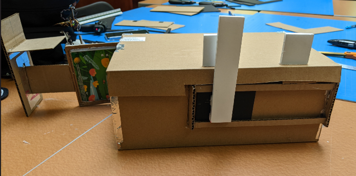
The actual cover will be a piece of black foam core fastened in between those two pieces and an extra two on top to hold it in place. On day five we completed the aperture cover finished with a handle that tells you if it is closed or opened. I finished working on the photo frame part of the film holder and now we started making the pull tab attachment that you must insert into the small inlet on the side of our box. On day six we finished the pull tab and patched up the box as much as possible for the coming development test. The barebones for our camera to work was done.

Initial Results
For our first development test, we went to the darkroom and inserted the blank film into our holder. We closed our entire box and took it outside for light to get in through any possible inlets that there might be. After some time, we took it back into the light room and started doing the development process. By putting the film into several types of liquid chemicals. Our Test strip (above) came out pretty dark mostly because the carboard is not fully light proof. That really black spot could be the small openings near the inlet for our film holder.
Modifications
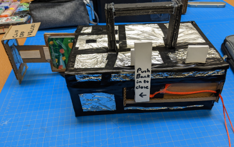
After that, we decided that because the box isn’t completely light proof, we should wrap it in aluminum foil. It will reduce the amount of light coming in.I ultimately chose to add some Velcro to the top and sides of the film holder. We also placed a black waste bag measuring 60 cm × 60 cm over it. We put aside the aperture closure and film holder while wrapping it in aluminum foil because you had to hide those with smaller items. After these modifications we did our second development test and the strip came out completely white, meaning there was no light penetration. We first took a picture of a gate about 10 ft long and had trees in the background. (see below)
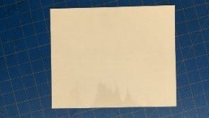
However, our exposure time was only 306 seconds, four times our calculated exposure time on a day with dense cloud cover. The picture came out mostly white even if you invert it, you only see some outline of trees in the background. We probably need to adjust our exposure time based on these results.
Subsequent Testing
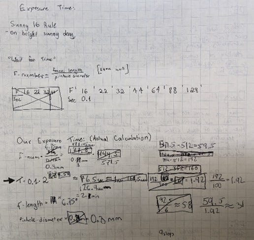
The next day we took another picture but kept the times 4 on our exposure time as it was a sunny day. This time we were taking a picture of a fire hydrant. The picture still came out exceptionally light even if used the same exposure time on a sunnier day! Finally, we realized that there was probably something wrong with our aperture itself. When we re-measured it, it came out as 0.3 mm; this was quite different than that of the 0.4 mm we measured when we cut out our pinhole on day two. Because of this, we had redone our exposure time calculations.
Final Product
We took a photo of the front of a school bus for our final image. Considering it was a cloudy day, we quadrupled the exposure duration to 8 minutes and 8 seconds. Even after all of this, our image turned out whiter than we expected. Even though the markings on the school bus may be seen, the genuine bus cannot be completely replicated on film paper. We thought the reason for this could be the lightness of yellow and how it is harder to capture with only so much time. Other than the actual picture, our camera met all the requirements of our client. It captured a 10 ft x 10 ft object. It could be used by people with hand dexterity, as we tested it out with oven mittens. It was also very inexpensive, as all our materials were things you could find in an art center.
5. Final Representation
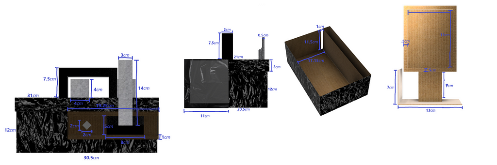
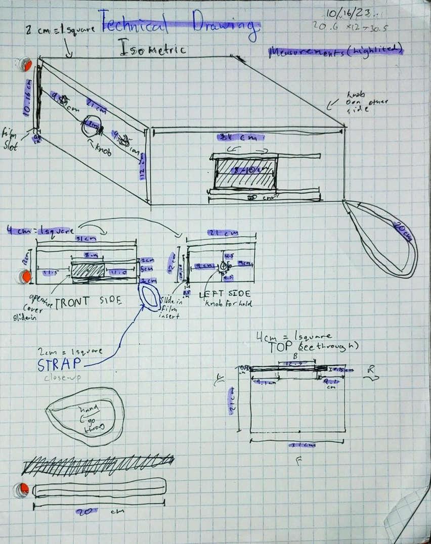
For our final report that we give to the user, we gave all the building instructions in a numbered list. We also gave instructions to use the camera. This document had all the critical product specifications which include the aperture size of 3 mm, the film size 10.16 cm x 12.7 cm, the focal length 17.15 cm, and our base exposure time of 127 seconds. We also gave the user all the tools and the exact sum of each of the materials used in the build. After looking through these resources our client, the art studio and its members can successfully build and use a pinhole camera.
6. Reflection
Looking back, this project turned out to be an exciting engineering challenge. We worked through each of the steps in our engineering design process, researching and finding user needs, then doing an analysis to designing, prototype building, testing, and finally, the retrospection. We went through multiple rounds of designing, testing, and working together to solve problems to meet the unique requirements of our customers who struggle with hand dexterity. Reflecting on the project we learned useful lessons from the mistakes and difficulties with communication we met. One notable occurrence was when we had issues with the film holder. Our first design did not adequately block light, resulting in leaks. This proved the importance of being willing to change your original design when things don’t go as planned. As a result, we quickly reinforced the weak points by integrating more materials. This small tweak made our design more light-tight, pointing out the importance of being able to adapt on the fly for the success of the project. Additionally, we met communication issues during the prototype building phase. Due to unclear communication about the design, my teammate and I had differing ideas on constructing the aperture cover. This made us see the need for better communication between us, a lesson learned for next time. Overall, the project broadened my understanding of how engineers work. It made visible the effects of well-executed design.