DOCUMENTATION AND ANALYSIS OF PRIOR SOLUTION ATTEMPT
Real World Technology
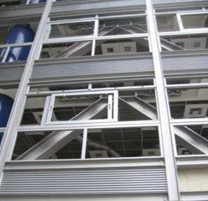
Our team looked at seismic bracing as a technology that could potentially reduce the risk of damage to our building during earthquakes. This technology involves installing support systems that can absorb and dissipate seismic energy, increasing the structural integrity of the building. There are many types of seismic bracing configurations, including cross-bracing, buckling-restrained braces, V-braces, and suspended zipper column braces. Each configuration offers unique advantages and can be tailored to the specific needs of the building. There are many examples of these techniques being used in the real world, such as in skyscrapers in earthquake-prone regions like Japan and California. We specifically researched the One Maritime Plaza in San Francisco, CA.
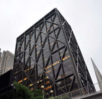
This building utilizes a structural steel framework consisting of two grids of 5- story high cross braces stacked atop one another. These bracing systems provide lateral stability by resisting horizontal forces generated during an earthquake. Some types of braces are designed as a fuse for the building during an earthquake. Earthquake forces attack the weakest link, and in this case, they are the braces. These braces are designed to absorb the energy from the earthquake, protecting the rest of the building from damage.
Relevance of Prior Solutions to Design Challenge
After our research, we decided that seismic bracing is the best earthquake resistant technology for our model building. We have a budget of $700,000, and we want something that is relatively easy to place on our building’s facade. Seismic braces absorb and distribute energy, preventing excessive swaying and maintaining stability. They are strategically positioned within the building’s structural framework to ensure effective load transfer. It strikes a balance between structural performance and cost, making it a viable option for most building types. We specifically chose V-bracing as it is a lot easier to fasten on the exterior compared to other types of bracing systems. We do not need to spend as much time and effort perfecting each measurement.
Research Sources
We looked at many places when researching seismic bracing techniques. These included websites developed for building design and technology. Architects and engineers all over the world use sites like the Whole Building Design Guide to gather information on the latest advancements in structural engineering. This allowed us to make an informed decision on the most suitable bracing system for our project.
PROTOTYPE TESTING AND DATA COLLECTION PLAN
Building Modifications Chosen:
· Two large middle beams
· “V” bracing
· Cross-bracing or additional skeletal beams
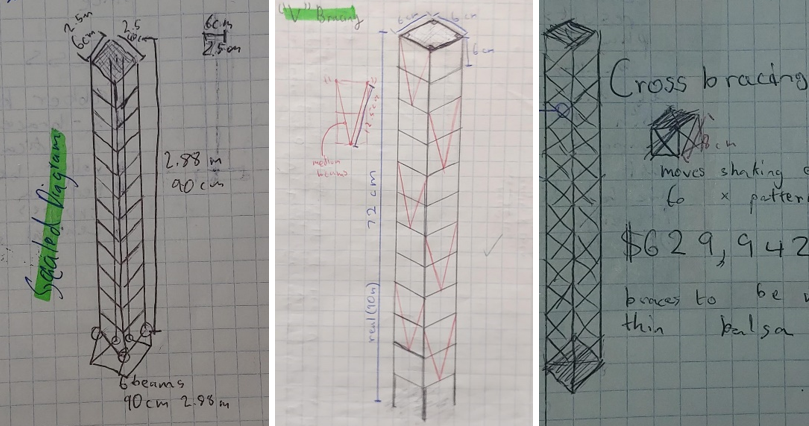
These modifications were chosen primarily based on their perceived effectiveness in improving earthquake resistance. After conducting research on specific earthquake resistant techniques, we were able to produce these three modifications that we believe will significantly enhance the building’s ability to withstand seismic activity. The two middle beams were chosen to be the structural core of our building. Most high-rise buildings have this to help support the weight of the building. We chose this to ensure maximum stability and structural integrity during earthquakes, as the core beams may play a crucial role in distributing forces and minimizing sway. In the case of V-bracing, we selected it due to its capability to provide lateral support and reduce the building’s vulnerability to horizontal movement during an earthquake. Cross-bracing is remarkably similar, and it is used in many real-world structures for the same purpose of enhancing stability and reducing the risk of collapse during seismic events.
Exclusions From Testing
Other techniques were excluded from testing because they were too complex and unproven for our small testing setup. Viscous dampers, which could have gone overbudget, would be overly complex to design and install in our original 12-story base case.
Other teams were putting in pendulums, which are essentially mass dampers. These solutions are effective in reducing the impact of seismic events on tall buildings, but they were not feasible for our testing purposes. It is important to consider cost, complexity, and practicality when choosing seismic retrofitting techniques for a specific structure.
Planning Testing
We split the testing for each modification into three separate phases. Phase one is conducted with one test per speed level of a shaker table, which simulates earthquakes. Phase two follows the same approach as phase one, but phase three includes three tests per speed level to capture a wide range of data under varying conditions, improving data reliability and accuracy.
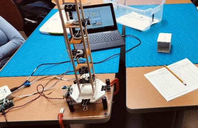
The test plan had some up sides, like taking a close look at distinctive designs to see how tweaks affect the building’s resistance to earthquakes. We ramped up testing slowly, going from one test per level to three in phase three, which helped us verify our data and fine-tune the results for the different techniques. Collaborating with other teams and sharing results also made for a great collaborative vibe and gave us a chance to cross-check our findings. However, this method of testing did come with its own drawbacks. A few trials may not have revealed all the strengths and weaknesses of each modification, which can be discovered through more thorough testing. Furthermore, human error could occur due to weight misplacement or insufficient balancing. If the building were too heavy, it would cause the motor to slow down and thus lead to skewed results.
TESTING, DATA COLLECTION AND ANALYSIS
Data Collected and Performance Metrics
We as a class collected a lot of data on how each modification of the base building behaved when it was put through the earthquake simulations.
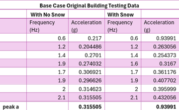
This involved taking measurements of the structures’ movement and their reactions to various stress levels. We then assessed which designs could withstand the most amount of shaking and maintain stability, and now we could tell which modifications worked well and which did not. We also examined how the buildings performed when extra weight, such as snow, was applied to them to simulate real-world conditions.
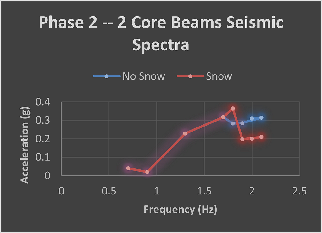
We also collected key metrics, which we could use to compare our specific modifications to the base building and other teams’ data. These comprised the peak acceleration and the resonance frequency. To evaluate the building’s response to seismic activity, the resonant frequency is crucial. This resonant frequency, at which the building shakes the most, can tell you what magnitudes will cause the most damage to a building. The simulation tool collects the frequency for every test, and using that, we can find where the resonance occurs. The peak acceleration measures the maximum amount of acceleration or shaking the building experiences during the simulation. This is measured using the accelerometers that plug into the shaker table set.
Data Analysis
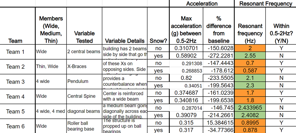
Our test results from phase two show that the two core beams did a lot better than the base structure. The data shows that the resonance occurred at 2.1 Hz. The peak acceleration for the building without snow was around 0.314 g, which was not particularly different from the base structure, which had an acceleration of 0.355 g. Our team’s design did a lot better than other designs in terms of structural stability during the simulation. As you can see, designs like the pendulum had a much higher peak acceleration, making them less stable under added weight at the top compared to our design. However, we saw that seismic bracing techniques only had a peak acceleration of about 0.291 g. As we researched, this design was effective in minimizing peak acceleration by dissipating the horizontal forces in simulated seismic conditions. The results indicate that our modifications were pretty successful in improving the building’s resilience to external forces. In conclusion, this class data suggests that implementing seismic bracing techniques can significantly enhance structural stability in buildings subjected to seismic conditions.
Factors Affecting Data Accuracy and Interpretation
There are a few sources of variability and potential errors in our data collection and analysis process that must affect how we interpret the results. Along with the errors discussed in the test plan, one major issue we as a team ran into was the inconsistency of our motor. Sometimes it did not run at the speed we needed, so the seismic spectra looked kind of wonky. That makes it hard to get accurate data. We risk making mistakes in our reasoning or misinterpreting our results if we analyze this data without taking those factors into consideration. So, we have got to be careful when we look at the data and keep these issues in mind.
CONSTRUCTION OF A TESTABLE PROTOTYPE
When making our final model, we aimed to pay close diligence. Our goal is not to have a design that falls flat because we failed to consider a minor but significant detail. Not only does the structure need to be visually beautiful, but it also needs to be structurally strong and earthquake resistant. We followed a detailed construction plan, maintaining strict standards to ensure that the finished model met our testing expectations.
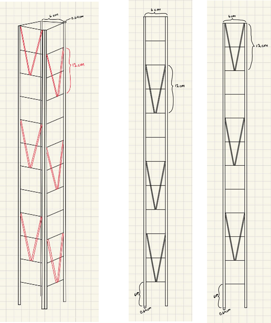
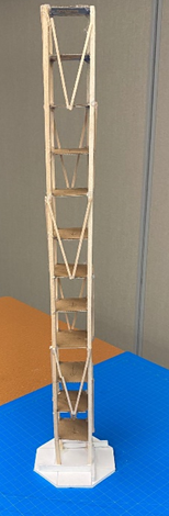
We chose V-braces as the main structural element in our final design. These braces span multiple levels, significantly increasing the building’s ability to withstand large shakes. We planned to have the V-braces placed in a way that they circle around the building. Our final design didn’t cost much as it was everything in the base structure plus medium sizes beams. These are supposed to be strong and rigid as they will take most of the force caused during the simulation.
Final Design Dimensioned Diagrams: The units where every grid square is equal to 2 centimeters.
Final Design Costs and Materials:

Construction Process
For constructing this, we used hot glue, balsa wood beams (both large and medium), a sheet of foamcore, utility knives for cutting, and rulers and pencils for measuring things.
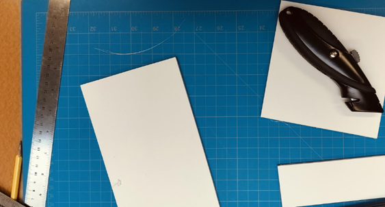
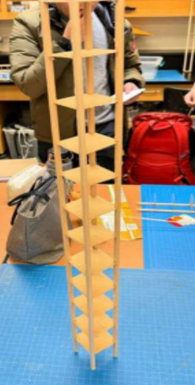
We started off by making the base case of the 12-story building. We cut out the four large beams, so each of them is 72 inches in length.
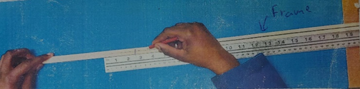
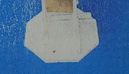
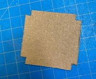
These were the frames that provided the necessary support for the building. Additionally, we carefully measured out and drew notches every six centimeters on the large beams, as that is where the floors of the building would be attached. Side by side, we marked the locations for the cuts on the 14 cm by 14 cm foamcore base. We did this by making four marks four cm away from the corners of our foundation and we cut the corners from those marks we made. The foamcore base was now octagonal and we drew two lines between the edges. We also sketched the design of the rectangular building supports on the same foamcore. We cut the supports out and set them aside so that when we get our final building done, we could glue them on.
We used cardboard cereal boxes to cut out 12 six cm by six cm squares as the floors. We also remembered to cut out the small 0.6 cm x 0.6 cm squares on each floor’s edges, which are crucial for sliding the large beams through.
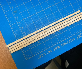
As we were using V-braces for our earthquake-resistant concept, we had to cut out Vs from the medium beams. Each half of the “V” measured 12.5 cm. We first marked these lengths on all four medium beams before cutting them out. There were exactly 24 cut out beams which gave us enough material for 12 usable Vs. We set these aside so we could assemble the main structure of the building.
Before gluing anything, we had to mark the direction of the cardboard’s grain. This step is crucial for the building’s stability. We did this by just drawing an arrow pointing which way the grain is going.
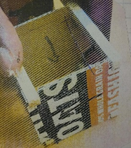
Before gluing anything, we had to mark the direction of the cardboard’s grain. This step is crucial for the building’s stability. We did this by just drawing an arrow pointing which way the grain is going. One by one, we hot glued the floors to two of the large beams, making sure that they were precisely positioned on the latches. We alternated the placement of each of the floors so that the grain goes vertically and then horizontally. We made sure to glue that 12th floor on one of the ends of the beam.
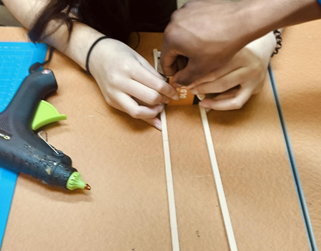
Once all 12 floors were attached to the first two frames, we repeated the process with the other two, taking care to align the smaller cuts on the floor’s edges with the latches.
Finally, it came down to gluing the 12 V-braces around the building. As mentioned in our plan, we couldn’t cover the entire building’s facade with braces. This was due to the budget and the fact that more braces could mean more error in the construction. So, instead of doing that we stuck to our plan of alternating the sides of the two floors where the Vs would go.
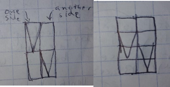
We used this same approach until we had to put the braces on the bottom two floors. Here, we ended up shifting one “V” up a floor to keep stability at the base. Lastly, we glued the final structure to the base by placing the building’s four large beams in the middle of the octagonal base. Then, we glued the supports in a pinwheel-like form around the building.
Difference Between Model and Actual Build
Our building mostly followed the original plan, but we had to make adjustments for stability. In a real build, these adjustments would likely be unnecessary due to stronger materials and construction techniques. Some included re-gluing a few of the braces as they would snap. The biggest problem we had in building our specific structure had nothing to do with the plan at all. Hot gluing together the beams and supports was a challenge, as the glue would often dry too quickly before we could properly align the pieces. This resulted in some sections being less secure than we would have liked.
CONSIDERATION OF DESIGN VIABILITY
V-braces ensure that the power of a quake passes smoothly down to the base, reducing weak points that may fail when things get nasty. They act as the fuse in an earthquake, absorbing the shock and preventing damage to the overall structure. In addition to all the technological benefits, these braces seem pretty cool, too. They let us throw in some creative design touches on the outside without messing with the building’s safety or how well it works.
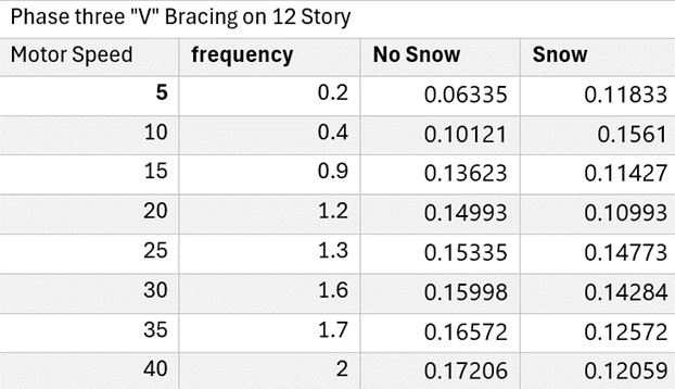
The V-bracing worked well for phase three, as our team’s peak acceleration was only in the 0.1s. For the building without snow, the resonant frequency was 2.0 Hz, as expected. However, as the snow adds more weight at the top, the building sways more, and thus, the resonant frequency was 1.3 Hz. This building would be considered safe for the most part. If you looked really closely at the building while testing, you could notice some smaller tremors. But for the most part, looking at it from a distance, the building appeared stable and secure during the simulation. However, we encountered a few problems with our motor during the testing of the snow. As a result, our frequencies and accelerations were pretty low. The acceleration was lower with snow on the top of the building than without it because the added weight at the top, combined with the strong base and the V-brace reinforced middle, created a balanced structure.
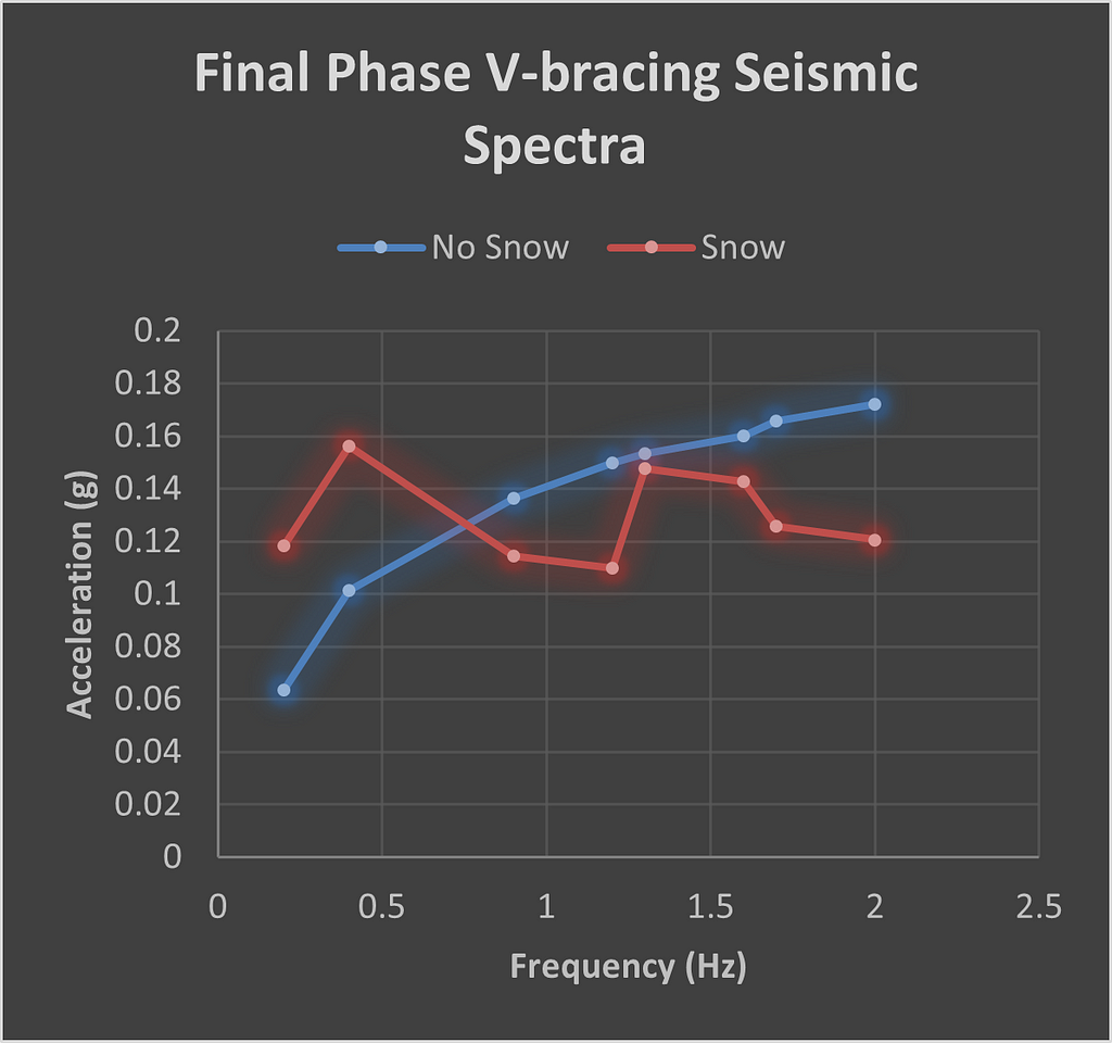
Our final design tower most definitely met the requirements and constraints set forth by the clients. The peak acceleration was more than 0.2 g lower than that of the baseline data. Our design almost eliminated any form of swaying or shaking. Although resonance occurred at 0.2 Hz, which aligns with the frequency of earthquakes in the area, the acceleration was too low to have any significant impact. The class decided a building would be defined as “safe” when the acceleration was between 0.18 and 0.34 g. Our team’s acceleration was significantly lower, measuring 0.17 and 0.14 g for the no-snow and snow tests, respectively. The final building met all constraints, including a minimum height of 12 stories, and we completed it with nearly $60,000 left in our budget.
The building boasts notable strengths, including a tremendously low peak acceleration, well below baseline data, and an unconventional spiral arrangement of braces ensuring stability from all sides. Its simplicity and adaptability to most building facades, combined with the project’s $60,000 cost savings, highlight its economic and structural benefits. However, weaknesses in the design were also identified, notably the fragility of the V-brace medium beam, which raised concerns about potential breakage under stress, leading to vibrations that could compromise the building’s interior integrity.
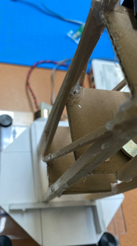
Additionally, the necessity of adopting a spiral brace pattern, primarily driven by budget constraints, deviated from our preference for a more uniform distribution. These observations highlight areas for potential enhancement in both the construction and design phases. For example, incorporating notches into the major beams could provide a more tailored fit for the V-braces, reducing reliance on adhesive and lowering the risk of breakage due to uneven surfaces. The design process revealed a missed opportunity to fully utilize V-braces, despite significant budget flexibility, because their placement lacked a carefully planned pattern. This underscores the need for us to adopt a more calculated approach to distributing braces to fully leverage available structural and financial resources.
CITATIONS
“Seismic Design Principles | WBDG — Whole Building Design Guide.” WBDG, wbdg.org/resources/seismic-design-principles. Accessed 11 Apr. 2024.
Prasad. “Earthquake-Resistant Building Design.” Structural Guide, 6 Nov. 2023, www.structuralguide.com/earthquake-resistant-building-design. Accessed 11 Apr. 2024.
Ubaid, Mohd, and Rehan Ahmed Khan. “Effect of Bracing Configuration on the Seismic Response of Buildings With Re-entrant Corners.” Innovative Infrastructure Solutions, vol. 8, no. 1, Jan. 2023, https://doi.org/10.1007/s41062-022-01029-x.